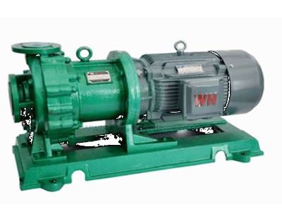
What Is a Magnetically Driven Centrifugal Pump
Magnetically driven, non-hermetic Centrifugal Pump uses a product within the pressure boundary to lubricate the bearing and the magnetic coupler to transfer torque throughout the sealed case, thus providing a complete seal to the process fluid.
Pump case is composed of suction and discharge flange and housing volute impeller. The rotation of the impeller transfers energy to the liquid to make the pump run. The impeller is supported by an internal pump shaft and shaft sleeve. The shaft is supported by a bushing retainer consisting of a rigid bearing and a bushing or bearing, which is close to the bushing.
The internal rotor ring is a complement to the internal rotor assembly. This is a coaxially arranged ring of outward-facing permanent magnets that is completely encapsulated by a resistive metal sheath. The last component of the liquid contact assembly is the containment. The assembly is statically sealed to the housing by a gasket. Containment vessels are usually made of high-strength, non-magnetic, corrosion-resistant alloys. Beyond the main pressure boundary is a second external magnetic ring in which the magnet faces inward. The outer magnetic ring is located in the coupling housing, and the coupling housing is connected to the external bearing assembly.
When the pump is filled or "filled", liquid can be completely filled without the use of any dynamic seals. The principle is very simple. The magnets in the outer and inner rings attract each other, so as the motor rotates, the outer and inner rings rotate at the same speed, causing the impeller to rotate and causing the liquid to be pumped.

Magnetic Drive Pump
A magnetic circuit located between two attractive magnetic rings and subject to rotation as the outer ring and the inner ring rotate. To improve strength and temperature resistance, containment vessels are usually made of electrically conductive metal. It is this property combined with the rotating magnetic circuit that causes the eddy currents to be induced in the housing. These induction losses appear as heat and must be taken into account when using the pump.
A small portion of the pumped fluid is also used to cool the magnetic coupler and lubricate the internal bearings. The pump uses the pressure generated by the impeller to send a small amount of pumping product to the rear of the pump. Here, the flow splits and a small portion of the flow lubricates the internal sliding bearing and returns to the pump case volute. Most of the fluid enters the hole in the pump shaft and flows to the rear of the containment vessel, where it splits radially backward and flows in a circulation between the internal magnetic ring and the containment vessel. As already mentioned, the metal casing has associated losses that require cooling, and it is this internal flow that provides this cooling. After flowing through the internal magnetic ring, the fluid returns to most of the fluid in the volute through the backflow hole behind the impeller.
It is important to understand the effect of Circulating Pump fluid in the internal feed system. As the liquid circulates, its pressure drops and temperature rises, and in order to operate safely and reliably, the liquid needs to remain stable at all times.
It has often been suggested that monitoring the condition of the internal flow will be of great help to the users of the Magnetic Drive Pump, especially in respect of steam content. However, the technicalities of implementing such a system have proved particularly challenging. Because the pressure boundary (casing) is surrounded by a rotating outer magnetic ring, the pump structure prevents the fluid from easily entering the pump as it circulates in the rear. In addition, if the boundary is breached in order to obtain the liquid, it will effectively lose its airtightness, so the non-invasive technique is preferred.


